Sunday, 28 February 2016

Lesson 8 Interfacing 7 Segment Display With PIC 16F877A (MikroC)

Seven Segment Display (SSD) is commonly used in counters, electronic meters, digital clocks, etc.
It is composed of 8 LEDs, 7 of the LEDs are arranged  in rectangular form to display numbers from 0-9 and also characters A-F. The 8th LED is for decimal point display.
There two types of SSD:
  • Common Cathode.
  • Common Anode.
In Common Cathode, all the cathode of the diodes are connected to a common pin. while in Common Anode, all the anode are connected to a common pin.
Segments are marked with a-g                                            
                                                 
    Each diode is treated separately, that is : when connecting it to a microcontroller, each diode must have its own limiting resistor. For you to display numbers or characters on SSD, the binary format of each digit must be replaced with different combination of bits (masking). For instance to display 2, which is 0000 0010 in binary it is replaced with 0110 1101. 

Here is a look up table for displaying 0 - F on a common cathode SSD.


By sending this numbers one after the other to the PORT where the SSD is connected, you have a counter from 0 - F . 
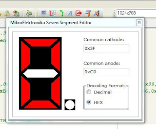
MikroC has SSD Editor which you can use to get this numbers for both common Cathode and Common Anode. On the Tool Bar click on  the 7 symbol and it will pop up.


MikroC Code:

/**********************************
Project Name :
   Interfacing of 7 segment display with PIC 16F877A
Author : Promise
Description :
   This project demonstrate how to interface 7 segment display with PIC 16F877A. it counts from 0 - F
Test configuration:
   MCU:  PIC 16F877A
   Oscillator: XT 8.0000 MHz, 8.0000 MHz Crystal
   Dev Board : Easy Pic v7
 turn on switches SW4.0, SW4.1, SW4.2, SW4.3
 For common Cathode 7 segment display, Uncomment count1[16]
***********************************/


unsigned int i;

//unsigned int count1[16] = {0x3F,0x06,0x5B,0x4F,0x66,0x6D,0x7D,0x07,0x7F,0x6F,0x77,0x7C,0x39,0x5E,0x79,0x71};  //array for common cathode display (0-15)

unsigned int count[16] = {0xC0,0xF9,0xA4,0xB0,0x99,0x92,0x82,0xF8,0x80,0x90,0x88,0x83,0xC6,0xA1,0x86,0x8E};  //array for common anode display (0-15)

void main() {

  TRISB  = 0x00;           //Configure PORTB as Outputs
  
  while(1) {
  
   for(i=0;i<16;i++){       // loop through array element
   PORTB = count[i];       // send arrray elemnts to PORTB
   delay_ms(500);
   }
   }
 }

Proteus Schematic for Common Anode:


Proteus Schematic for Common Cathode:


Saturday, 27 February 2016

Lesson 7 Interfacing Servomotor with PIC 16F877A - MikroC


Servos are used in cars, boats, helicopters, robots etc. They are geared DC motors with positional feedback control that allows for the rotor to be accurately positioned. The gear drives the output shaft and also control an internal potentiometer. The potentiometer feeds back the output shaft position to the internal control devices that control the DC motor. Servos can be rotated through 180 degrees (+ or - 90 degrees) though its internals can be modified to give full 360 degree rotation.

It has 3 wires: power (5v), ground, and the control wire. By sending pulse width signals to the control wire, the shaft can be rotated. The pulse can be varied from 1 - 2 miliseconds.
1 ms will rotatae the shaft counter clockwise (-90 degrees).
1.5 ms will rotate the shaft to its neutral axis (0 degrees)  
2 ms will rotate the shaft in clockwise direction (+90 degrees).
Any pulse width in between moves  the shaft between these positions (+ or - 90 degrees)


        MikroC Code:
     
/**********************************
Project Name :
   Interfacing Servomotor with PIC 16F877A
Author : Promise
Description :
   This project demonstrate how to interface a servomotor with PIC 16F877A. It rotates back and forth (CW and CCW) continuously

Test configuration:
   MCU:  PIC 16F877A
   Oscillator: XT 8.0000 MHz, 8.0000 MHz Crystal
***********************************/

unsigned i ;

void main() {

TRISB.B0 = 0;             // set PORTB bit zero to output

while(1){

for(i=0;i<100;i++){        // rotate to neutral axis (0 degree)
PORTB.B0 = 1;
delay_us(1500);             // generate 1.5ms pulse
PORTB.B0 = 0;
  delay_ms(20);            // 50Hz frequency for servo to react
}

for(i=100;i<200;i++){     // rotate CounterClock wise CCW (-90 degree)
PORTB.B0 = 1;
delay_ms(1);              // generate 1ms pulse
PORTB.B0 = 0;
  delay_ms(20);           // 50Hz frequency for servo to react
}

for(;i>100;i--){         // rotate ClockWise CW (+90 degree)
PORTB.B0 = 1;
delay_ms(2);             // generate 2ms pulse
PORTB.B0 = 0;
 delay_ms(20);           // 50Hz frequency for servo to react
}
}
}

Proteus Schematic: