In this lesson we will try to explain to you how you can
use your Flowcode program to work with the PWM by using it to control the
brightness of an LED with the aid of an ADC..
Like it was explained in the Mikro c lesson that the Pulse Width Modulation (PWM) is a technique
where digital input is used to control the amount of power transferred to
a load . This can be used to control motor speed, LED brightness and so on. So with much explanations done in the previous post under
the Mikro c lesson, we are just going to go straight to the point by showing you
the step by step procedure on how to go about doing the same using the Flowcode
software.
- Run the Flowcode application.
- Click on the 'OK' button when the reminder screen opens.
- Next you have the option of creating a new Flowcode flowchart, or opening an existing one. Select the option to create a new one
- You now have to choose a target PIC chip. The 44-pin Demo Board is fitted with a PIC 16f877A, so choose that from the list.
- A new workspace called 'Main Opens' .
- You then select the ADC component from the inputs menu and also the PWM component from the mechatronics menu which will look like this.
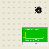
- After the selection has been done, we then configure them which is by setting the ADC component in ADC channel AN0.Also the PWM configuration will look like this


- Then click and drag the icons from the icons toolbar running down the left-hand edge of the screen, to make the Flowcode flowchart shown below. For the moment , do not worry about configuring them-we will do that next.

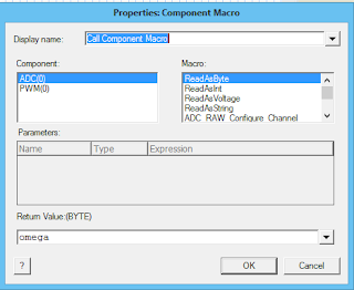
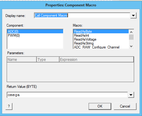
- Now we then add the component macro icon,select the ADC ReadAsByte and create a new variable(You can name it whatever you want) but here it was given the name 'omega'.
- Next we again select the component macro icon, select the PWM SetDutyCycle and give it the variable we had initially created as shown below.

- We again select the component macro icon, select the ChangePeriod and give it the period register 255 and prescaler divide 1 as shown below.


- We still again choose the component macro icon, select the PWM and set it to Enable as shown below.


- We then select our while loop icon and edit as shown below.


- So therefore inside this while loop we then pick again a component macro icon,set it to ADC ReadAsByte and give it the variable name you had initially set exactly like the one created before, also choose another component macro icon , set it to PWM SetDutyCycle and give it the same variable name also like the one created initially.


- When all these as been done you can then run your program.The full Flowcode flowchart and components should look like this below.

good work hoope 4 more
ReplyDelete