Liquid Crystal Display(LCD) is used for displaying messages. In this tutorial we are using 2x20 LCD. It has 2 lines and 40 characters per line. Only the first 20 characters of each line are visible. The LCD has 14 pins plus 2 additional pins for its backlight.
You can watch or download the video here
Thursday, 23 July 2015
Flowcode Lesson 4 Forward and Backward blinking of LED array
In this tutorial we are going to show you how you can use flowcode to make an array of LED to blink Forward and Backward.
You can watch or download the video here.
You can watch or download the video here.
Flowcode Lesson3 Switch Controlled LED
In this tutorial we're going to show how a push button switch is used to turn ON and OFF a LED using the flowcode software. The target MCU is PIC 16F877A.
You can watch or download the video here .
You can watch or download the video here .
Tuesday, 21 July 2015
Flowcode Lesson 2 ADC and PWM with PIC 16f877A
In this lesson we will try to explain to you how you can
use your Flowcode program to work with the PWM by using it to control the
brightness of an LED with the aid of an ADC..
Like it was explained in the Mikro c lesson that the Pulse Width Modulation (PWM) is a technique
where digital input is used to control the amount of power transferred to
a load . This can be used to control motor speed, LED brightness and so on. So with much explanations done in the previous post under
the Mikro c lesson, we are just going to go straight to the point by showing you
the step by step procedure on how to go about doing the same using the Flowcode
software.
- Run the Flowcode application.
- Click on the 'OK' button when the reminder screen opens.
- Next you have the option of creating a new Flowcode flowchart, or opening an existing one. Select the option to create a new one
- You now have to choose a target PIC chip. The 44-pin Demo Board is fitted with a PIC 16f877A, so choose that from the list.
- A new workspace called 'Main Opens' .
- You then select the ADC component from the inputs menu and also the PWM component from the mechatronics menu which will look like this.
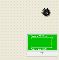
- After the selection has been done, we then configure them which is by setting the ADC component in ADC channel AN0.Also the PWM configuration will look like this


- Then click and drag the icons from the icons toolbar running down the left-hand edge of the screen, to make the Flowcode flowchart shown below. For the moment , do not worry about configuring them-we will do that next.

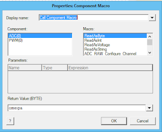
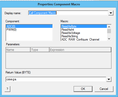
- Now we then add the component macro icon,select the ADC ReadAsByte and create a new variable(You can name it whatever you want) but here it was given the name 'omega'.
- Next we again select the component macro icon, select the PWM SetDutyCycle and give it the variable we had initially created as shown below.

- We again select the component macro icon, select the ChangePeriod and give it the period register 255 and prescaler divide 1 as shown below.


- We still again choose the component macro icon, select the PWM and set it to Enable as shown below.


- We then select our while loop icon and edit as shown below.


- So therefore inside this while loop we then pick again a component macro icon,set it to ADC ReadAsByte and give it the variable name you had initially set exactly like the one created before, also choose another component macro icon , set it to PWM SetDutyCycle and give it the same variable name also like the one created initially.


- When all these as been done you can then run your program.The full Flowcode flowchart and components should look like this below.

Sunday, 19 July 2015
Lesson 6 LCD Scrolling Display With PIC 16F877A (MikroC)
In the previous tutorial, we talked about a 2x16 LCD, the number of pins it has and their various functions. We also discussed on its different connection mode. Do well to go through the previous tutorial (Lesson 5 MikroC) to get acquainted with it.
Here we are going to create a Scrolling Message on an LCD, which is very easy to achieve given the rich set of Library functions in MikroC. Lets get started with the program.
MikroC Code:
/**********************************
Project Name :
Scrolling display with LCD
Author : Promise
Description :
This project demonstrate how to Make scrolling Message on an LCD
Test configuration:
MCU: PIC 16F877A
Oscillator: XT 8.0000 MHz, 8.0000 MHz Crystal
***********************************/
// Lcd pinout settings
sbit LCD_RS at RB0_bit;
sbit LCD_EN at RB1_bit;
sbit LCD_D4 at RB4_bit;
sbit LCD_D5 at RB5_bit;
sbit LCD_D6 at RB6_bit;
sbit LCD_D7 at RB7_bit;
// Pin direction
sbit LCD_RS_Direction at TRISB0_bit;
sbit LCD_EN_Direction at TRISB1_bit;
sbit LCD_D4_Direction at TRISB4_bit;
sbit LCD_D5_Direction at TRISB5_bit;
sbit LCD_D6_Direction at TRISB6_bit;
sbit LCD_D7_Direction at TRISB7_bit;
// End LCD module connections
char txt[] = "WELCOME TO OUR..." ;
char txt1[] = "BLOG!!!" ;
char txt2[] = "www.mechatronicsandyou.blogspot.com" ;
void main() {
Lcd_Init(); // Initialize LCD
Lcd_Cmd(_LCD_CLEAR); // Clear display
Lcd_Cmd(_LCD_CURSOR_OFF); // Cursor off
Lcd_Out(1,1,txt); // output display
Lcd_Out(2,6,txt1);
delay_ms(3000);
Lcd_Cmd(_LCD_CLEAR); // Cursor off
Lcd_Out(1,1,txt2); // output display
delay_ms(500);
while(1){ //endless loop
Lcd_Cmd(_LCD_SHIFT_LEFT); // shift display to left
delay_ms(100);
}
}
Proteus Schematic:
 |
| Scrolling display with LCD in 4 bits mode |
Lesson 5 LCD Interfacing With PIC 16F877A (MikroC)
LCD Interfacing With PIC 16F877A (MikroC)
Liquid Crystal Display(LCD) is used for displaying messages. In this tutorial we are using 2x16 LCD. It has 2 lines and 40 characters per line. Only the first 16 characters of each line are visible. The LCD has 14 pins plus 2 additional pins for its backlight.

2x16 LCD
LCD CONNECTION
Liquid Crystal Display(LCD) is used for displaying messages. In this tutorial we are using 2x16 LCD. It has 2 lines and 40 characters per line. Only the first 16 characters of each line are visible. The LCD has 14 pins plus 2 additional pins for its backlight.
2x16 LCD
- Vss is the ground pin (0V)
- Vdd is the power supply (5v)
- Vee is LCD contrast (0-5V)
- RS is Register Select
- R/W is Read/Write pin (allows data to be written to or read from an LCD)
- E is Enable pin (enables/disable access to LCD)
- D0 - D7 are data lines
It can be connected in two ways :
- 8 bit Mode
- 4 bit Mode
4 bit mode uses only upper 4 bits (D4 - D7) and the lower data lines are left unconnected. Thus saving MCU I/O pins.
Vee is normally connected to a potentiometer to vary LCD contrast.
R/W is connected to the ground since data is rarely read from the LCD.
MikroC has LCD library functions which makes writing the code very easy. You can check out the library functions and how to use them from MikroC help files. Search for LCD library
** Ensure to check LCD in the library manager to avoid errors when compiling.
*** For the LCD backlight pins, a limiting resistor should be connected to one of the pins during operation.
MikroC Code;
/**********************************
Project Name :
LCD Display
Author : Promise
Description :
This project displays text on the LCD
Test configuration:
MCU: PIC 16F877A
Oscillator: XT 8.0000 MHz, 8.0000 MHz Crystal
***********************************/
// Lcd pinout settings
sbit LCD_RS at RB0_bit;
sbit LCD_EN at RB1_bit;
sbit LCD_D7 at RB7_bit;
sbit LCD_D6 at RB6_bit;
sbit LCD_D5 at RB5_bit;
sbit LCD_D4 at RB4_bit;
// Pin direction
sbit LCD_RS_Direction at TRISB0_bit;
sbit LCD_EN_Direction at TRISB1_bit;
sbit LCD_D7_Direction at TRISB7_bit;
sbit LCD_D6_Direction at TRISB6_bit;
sbit LCD_D5_Direction at TRISB5_bit;
sbit LCD_D4_Direction at TRISB4_bit;
// End LCD module connections
char txt[]= "WELCOME TO OUR " ;
char txt1[]="BLOG!!!";
void main() {
Lcd_Init(); // Initialize LCD
Lcd_Cmd(_LCD_CLEAR); // Clear display
Lcd_Cmd(_LCD_CURSOR_OFF); // Cursor off
while(1){ //endless loop
Lcd_Out(1,1,txt); // Output txt
Lcd_Out(2,6,txt1); // outut txt1
}
}
Proteus Schematic:
 |
| LCD in 4 bits mode |
Friday, 17 July 2015
Lesson 4 PWM to Control Brightness of an LED (MikroC)
In Lesson 3, we made mention of how PWM can be used to control LED brightness and motor speed control. In this tutorial we'll see how we can use it to Control the brightness of an LED. We advice that you check out Lesson 3(MikroC) before going through this tutorial in order to have an understanding of PWM. So let's get over to the program.
MikroC Code:
/**********************************
Project Name :
Using PWM to control LED brightness
Author : Promise
Description :
This project demonstrate how to use PWM to control the brightness of an LED
Test configuration:
MCU: PIC 16F877A
Oscillator: XT 8.0000 MHz, 8.0000 MHz Crystal
***********************************/
int i;
unsigned short duty_cycle;
void main() {
TRISC = 0x00; // PORTC set as output
PORTC.F2 = 0; // Set PORTC to Zero(low)
PWM1_Init(5000); // PWM1 Initalized to 5KHz
PWM1_Start(); // Start PWM1
while(1) { // endless Loop
for(i=0;i<255;i++){ // loop to increase LED brightness
duty_cycle = i; // Assign Counter(i) to the duty_cycle
PWM1_Set_Duty(duty_cycle); // Set duty Cycle
delay_ms(5);
} // end of for-loop
delay_ms(5); // delay
for(;i>0;i--){ // loop to decrease LED brightness
duty_cycle = i;
PWM1_Set_Duty(duty_cycle);
delay_ms(5);
} // end of for-loop
delay_ms(10);
}
}
Proteus Schematic:
 |
| When Duty Cycle is Almost 0% |
 |
| When Duty Cycle is Almost 100% |
Thursday, 16 July 2015
Lesson3 Push Button & PWM With PIC 16F877A (MikroC)
Pulse Width Modulation (PWM) is a technique where digital input is used to control the amount of power transferred to a load. This can be used to control motor speed, LED brightness etc.
Modulating the duty cycle varies average DC value of the signal can be varied. The energy delivered depends on the ratio of ON and OFF time as well as the frequency of the pulses.
Pulse Width: refers to the amount of time the signal is high.
Duty Cycle: refers to the ratio of ON time to the total time period. It is expressed in Percent, 0% means signal is OFF, 50% means equal ON and OFF time, 100% means signal is high. Other values can be calculated by:
(Percent / 100) * 255 (for 8 bit Resolution)
for e.g to have a 75% duty cycle, (75/100) *255 = 192
PWM is done with the CCP Module in PIC Microcontrollers. CCP stands for Compare Capture Pulse Width Modulation.
MikroC has a rich set of Library Functions to perform this task easily.
MikroC PWM Functions:
- PWMx_Init
- PWMx_Start
- PWMx_Set_Duty
- PWMx_Stop
You can read more about this library functions from MikroC help file.
** Before Using this functions make sure that PWM is checked in the Library manager.
*** Remember to check your datasheet to know the port pin associated with each pwm module
MikroC Code:
/**********************************
Project Name :
Push Button & PWM with 16F877A
Author : Promise
Description :
This project demonstrate using of push button to vary the duty cycle of PWM on CCP1 (PORTC Bit2)
Test configuration:
MCU: PIC 16F877A
Oscillator: XT 8.0000 MHz, 8.0000 MHz Crystal
***********************************/
unsigned short current_duty;
void Init() {
CMCON = 0x07; // turn off Comparator
ADCON1 = 0x06; // digital input
PORTA = 0;
TRISA = 255; // configure PORTA pins as input
PORTC = 0; // set PORTC to 0
TRISC = 0; // PORTC pins as output
PWM1_Init(5000); // Initialize PWM1 module at 5KHz
}
void main() {
Init();
current_duty = 200; // current_duty initial value
PWM1_Start(); // start PWM1
PWM1_Set_Duty(current_duty); // Set current_duty for PWM1
do { // endless loop
if (PORTA.B0==1) { // button on RA0 pressed
Delay_ms(20); // Switch debounce
if (PORTA.B0==1){
current_duty++; // increment current_duty PWM1_Set_Duty(current_duty); // Set duty to Current Duty delay_ms(10); }
} if (PORTA.B1==1) { // button on RA1 is pressed Delay_ms(20); if (PORTA.B1==1) {
current_duty--; // decrement current_duty PWM1_Set_Duty(current_duty); delay_ms(10); } } if(current_duty==255){ current_duty = 200; PWM1_Set_Duty(current_duty); Delay_ms(5); // slow down } } } while (1); }
Proteus Schematic :
 |
Saturday, 4 July 2015
Flow code lesson 1 LED interfacing with PIC 16f877A
In this example we develop a system that accepts a LED to
blink and run continuously.
NOTE : The flowcode version used here is (version 5)- · Run the flowcode application.
- · Click on the OK button when the reminder screen appears.
- · Next you have the option of creating a new flowcode flowchart, or opening an existing one. Select the option of creating a new one.
- · You now have to choose a target PIC chip. The 44-pin Demo Board is fitted with a PIC 16f877a, so choose from that list.
- · A new workspace is created called ‘Main’ opens. Click and drag icons from the icons Toolbar running down the left hand, edge of the screen to make the flowcode chart shown below. For the moment don’t worry about configuring them – we will do that next.

- · Now add the hardware. Click on the LED icon in the components Toolbar, running just inside the icon Toolbar. You now have the led component in the workspace.
- · Select the LED component in the workspace, click on the drop down menu button and select the component connection option. In the’ connect to port’ menu, the port A is already selected. So therefore the single LED is now connected on the port A bit 0 of the PIC. It should look like the following.

- · Then select the calculation icon and create a new variable constant and name it whatever name you desire ‘led_limt’. Also you can select the variable type you want, byte is the appropriate variable type e to use in this scenario. It must look like the one shown below.

·
Then next you then go to your calculations
workspace and equate your variable name to zero. Reason because your led is
starting from an OFF position which is zero. Your program must look like the
one below.

·
After that has been done you then move to your
delay icon add type in the amount of time you want your program to delay depending
on your choice, but make it a reasonable delay so the LED blinking can be
visible.

·
You then call your component macro so as to tell
the LED what to do. You’ll then select ‘LEDON’ just as shown below.

·
You’ll then put a delay icon again so as to give
our program the effect of the blinking.
·
Then you call the component macro icon again and
set it this time around to ‘LEDOFF’

·
Then you again add your delay icon and put in
your desired delay seconds
NOTE: your delay time must be the same throughout for
uniformity sake.
·
Now you can simulate your program

Subscribe to:
Comments (Atom)