In this example we develop a system that accepts a LED to
blink and run continuously.
NOTE : The flowcode version used here is (version 5)- · Run the flowcode application.
- · Click on the OK button when the reminder screen appears.
- · Next you have the option of creating a new flowcode flowchart, or opening an existing one. Select the option of creating a new one.
- · You now have to choose a target PIC chip. The 44-pin Demo Board is fitted with a PIC 16f877a, so choose from that list.
- · A new workspace is created called ‘Main’ opens. Click and drag icons from the icons Toolbar running down the left hand, edge of the screen to make the flowcode chart shown below. For the moment don’t worry about configuring them – we will do that next.
- · Now add the hardware. Click on the LED icon in the components Toolbar, running just inside the icon Toolbar. You now have the led component in the workspace.
- · Select the LED component in the workspace, click on the drop down menu button and select the component connection option. In the’ connect to port’ menu, the port A is already selected. So therefore the single LED is now connected on the port A bit 0 of the PIC. It should look like the following.
- · Then select the calculation icon and create a new variable constant and name it whatever name you desire ‘led_limt’. Also you can select the variable type you want, byte is the appropriate variable type e to use in this scenario. It must look like the one shown below.
·
Then next you then go to your calculations
workspace and equate your variable name to zero. Reason because your led is
starting from an OFF position which is zero. Your program must look like the
one below.
·
After that has been done you then move to your
delay icon add type in the amount of time you want your program to delay depending
on your choice, but make it a reasonable delay so the LED blinking can be
visible.
·
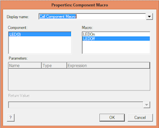
You then call your component macro so as to tell
the LED what to do. You’ll then select ‘LEDON’ just as shown below.
·
You’ll then put a delay icon again so as to give
our program the effect of the blinking.
·
Then you call the component macro icon again and
set it this time around to ‘LEDOFF’
·
Then you again add your delay icon and put in
your desired delay seconds
NOTE: your delay time must be the same throughout for
uniformity sake.
·
Now you can simulate your program


No comments:
Post a Comment